The Basics of CNC

 Research into the basics of CNC
 
The main method of part programme creation is G-code, this is the most widely use programming language in the engineering industry.
 The machine control unit (MCU) acts as the centre of a CNC system as it is used to perform functions such as:
Reading coded instructions
Decoding these instructions
Putting interpolations into place in order to generate axis motion commands
Receiving signals of position and speed
 Data can be transferred to and from the machine by using wired or wireless network connections in many modern machines, other methods of data transferring includes Bluetooth and using standard V24, RS232, or RS485 serial interfaces.
 Datum positioning can be done in a number of ways, one of the more common ways which does not require expensive equipment but is still accurate is using a dowel pin. To do this you go to an external edge using shim paper and slowly moving the dowel pin in until the dowel touches the shim on the edge of the material. Once you have done this you take half the diameter of the and use this to set the datum. Another method of datum positioning for centre line setting is probing two outside edges along one axis, taking the coordinates and finding the centre point going half way between them. 
 The main method of CNC machine programming is G-code, this is the most widely use programming language in the engineering industry. G-code includes different letter address variables which have different meanings, for example and F variable defines the feed rate and O variable is the program name.
 Feeds and speeds can be decided by using a feeds and speeds calculator, the variables that decide the feeds and speeds to be used are based on the hardness of material, cut size, type of tip, the overall condition of the machine (how often it is serviced), the life of the tool being used, angle of cut, cross section of chip, finish desired and whether coolant is being used and what type of coolant it is.
The position of the cutting tool is controlled by the MCU which receives and puts out codes, the programme inputs codes to the MCU which is then decoded and used for positioning and speed of the cutting tool.
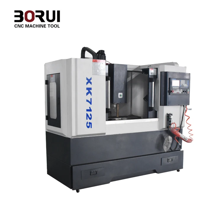
Xk7125 Borui Brand Small Cnc Mill Milling Machine Metal 240v - Buy ...
3 Axis CNC Milling Station
 

Comments

Popular posts from this blog

Impacts of a poor customer design process on customer relationships and requirements

The possible impact of a poor customer design process on customer relationships and requirements      Poor design process can have serious negative effects on a company relationship with their customers. A common occurrence in business is poor communication between the customer and the business. Poor communication in the customer design process may involve improper consideration of information passed on by the customer, this means the completed product is likely to not be of the standard/specifications requested. This can be caused by lack of technical specification or the company simply not following the technical specification, this is due to the technical specification being the most important part in the design process due to it containing so much vital information. If the technical specification is not used/followed then the end product is very likely to not match the customer’s requirements. A finished product that doesn’t match the customer’s requirements will like...

Hand Drawn Sketches vs Computer Aided Design

Hand drawn (sketches and orthographic drawings)        One major advantage of hand drawn designs is that it does not require any special training to do unlike other processes, this means that for quick drawings in the workshop they can be completed by anyone, even if they are not a trained design engineer. Unlike some CAD drawings, these hand drawn designs cannot be tested so you cannot gather vital information such as weight and conduct strength tests like you can when using CAD, this can have a major impact on the finished product as there is a higher chance of it having to go through redesign. Manual calculation is needed to work out cost calculations which can be quite time consuming and has risk of human error. In comparison to other methods, manual drawings are extremely time consuming especially if you have to draw out parts that are very similar with small differences as with CAD you can just copy the parts and add the differences in with ease.    ...

How 3D CAD models can be used in the design process

How 3D CAD models can be used in the design process ⦁ 3D CAD models can be used to replace the manual drafting processes with a more automated process, it allows you to visualize the design from different angles and analyse the feasibility of its working. By visualizing the design you can easily spot and flag mistakes in it and witness the entire design before it has been manufactured so it removes some of the need for rapid prototyping. ⦁ A wide variety of 3D software can be used for different types of simulation, mechanical design and analysis. Kinematics programs have many different tools which allow you to test the way that a part functions and allows you to see it working before it is manufactured, this can be extremely effective for spotting issues with how the parts function with each other as sometimes there are collisions in moving parts. Some of this software has a tool called the mechanism tool which will automatically tell you if it thinks the parts are not interacting ...